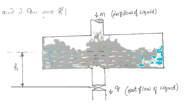
Such a diagram is used in engineering to show the main part of the system. In thermodynamics, this type of diagram and in mechanics this type of diagram is called a free body diagram and in automatic process control, it is called a physical diagram.
Note- The main purpose of this diagram is to show the flow of material and energy.
{tocify} $title={Table of Contents}
Fig shows a physical diagram in which m is an inflow q is an outflow and fluid is being stored in a vessel.
Block Diagram
Block diagrams are used to show the functional relationships among the various components of a process. In these, the elements are represented by circles and rectangular boxes.
(i) The circle box represents the algebraic function of the element.
Algebraic function [z = x - y]
(ii) Shows the dynamic function of the Rectangular box element.
Y = f ( x, t)
Here variable X is shown as input and variable Y is shown as output, both are functions of time.
Note- The flow of mass and energy cannot be shown by the block diagram.
Differences Between Physical and Block Diagrams
Physical and block diagrams are different types of visual representations used in various fields, including engineering, science, and technology.
Physical Diagram
1. It shows the main part of the system.
2. It shows the flow of energy and material in the system.
3. It does not tell the relation between the variables of the system.
5. This line is shown in the diagram and the diagram is real.
Block Diagram
1. It establishes functional relationships among the various components of the system.
2. It denotes the behaviour of the system.
3. It tells the relation.
4. The rectangular and circle are displayed by connecting them with arrows.


